
In the world of industrial automation and mobile machinery, hydraulic systems are the “muscle” behind heavy-lifting and precise movements. At the heart of every such system lies the Hydraulic Power Unit (HPU). It is an integrated assembly that converts mechanical energy into hydraulic power, providing the necessary flow and pressure to drive actuators like cylinders and motors.
To truly master hydraulic system design or troubleshooting, one must understand the individual components that make up a robust HPU. Here is a technical breakdown of the essential elements.
The Anatomy of an HPU: Key Components
A standard HPU is more than just a pump and a motor; it is a sophisticated “power plant” consisting of several critical subsystems.
1. The Prime Mover
The prime mover provides the initial mechanical energy. Depending on the application environment, this is typically:
- Electric Motors: The standard choice for stationary industrial applications (factories, presses).
- Internal Combustion Engines: Used for mobile or remote applications where electricity is unavailable (construction sites, agricultural machinery).
2. The Hydraulic Pump
The pump is the “heart” of the HPU. Driven by the prime mover, it draws hydraulic fluid from the reservoir and pushes it into the system.
- Common types: Gear pumps (cost-effective), Vane pumps (quiet operation), and Piston pumps (high pressure and efficiency).
- The pump’s performance is measured by its flow rate (L/min or GPM) and its ability to withstand specific operating pressures.
3. The Reservoir (Oil Tank)
The reservoir is much more than a storage container. Its design affects the longevity of the entire system by performing these functions:
- Fluid Storage: Holding enough oil for the system’s duty cycle.
- Heat Dissipation: Acting as a primary heat exchanger to cool the oil.
- De-aeration: Allowing air bubbles to escape the fluid before it re-enters the pump.
- Contaminant Settling: Letting heavier particles settle at the bottom away from the suction line.
4. Control Valves (The “Brain”)
Valves manage the power generated by the pump. They are categorized into three main types:
- Directional Control Valves: These determine where the oil goes (e.g., extending or retracting a hydraulic cylinder).
- Pressure Control Valves (Relief Valves): These set the maximum system pressure, protecting components from catastrophic failure due to over-pressurization.
- Flow Control Valves: These regulate the speed of the actuators by limiting the volume of oil passing through the circuit.
5. Filtration and Conditioning
Cleanliness is the lifeblood of hydraulics. Modern HPUs include:
- Suction Strainers: Protecting the pump from large debris.
- Return Filters: Cleaning the oil as it returns to the tank to ensure the reservoir stays uncontaminated.
- Breathers: Filtering the air that enters the tank as the oil level fluctuates.
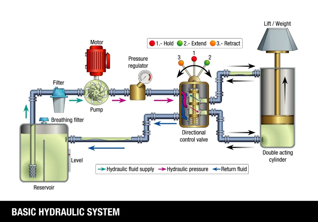
How It All Works Together
When the HPU is engaged, a specific sequence occurs:
- The Prime Mover spins the Pump.
- The Pump creates a vacuum at the inlet, drawing oil from the Reservoir.
- Pressurized oil is sent toward the Control Valves.
- The Valves direct the oil to the external Actuators (Cylinders/Motors) to perform work.
- Used oil returns through a Filter back into the Reservoir to be cooled and reused.
Summary
A well-engineered Hydraulic Power Unit is defined by the synergy of its parts. From the raw power of the prime mover to the precision of the control valves, each component must be sized correctly to ensure efficiency and reliability. For professionals in foreign trade and hydraulic manufacturing, understanding these technical nuances is the key to delivering high-performance solutions to global clients.

